- absolutely no background in robotics,
electronics, or programming needed
- some assembly required
- use of eyes NOT required
- batteries not included
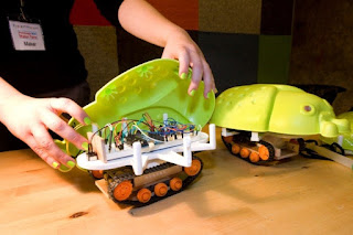 |
| My first robot, the Luna Moth Bot, on exhibit at the Pittsburgh Mini Maker Faire 2011. The microcontroller, motor control circuit, breadboard, and tank treads are housed under a repurposed SMILA BAGGE plastic lamp enclosure from IKEA that is about 12 by 9 inches. The photoresistor sensors (more on those later) are sized to fit perfectly into the winged bug’s eye sockets. Note that my nail polish matches the robot enclosure. The neon light green color is similar to that of a luna moth, the inspiration for the project. Photo credit: Larry Rippel |
Pfft... you think I could build a robot?
There is a certain mystique surrounding the word robot. For some it can conjure up delightful images of a friendly companion who is always eager to serve you; for others it causes fear of the unknown. When I think about robots, I think about machines that react to sensors. I tend to consider whether the functionality of a machine seems to be greater than the sum of all of its parts. Yes, that’s vague, but robotics is an incredibly diverse field and I couldn’t possibly hope to address it all. So, I’d like to focus on a very specific and accessible branch of robotics: hobby robotics. I’ll define a hobby robot as a robot built for fun or entertainment. It should mostly be an instructional device or something that you just think performs a cool function in some way.
Recent advances have made hobby robotics accessible to anyone with an interest, regardless of background or past experience. All you might need is a little bit of information about the hobby robotics community, a little background information that will make beginner guides more accessible, and a plan for moving forward. Though this guide is for anyone, I’ll be giving special attention to the readers interested in getting into electronics who are blind or have vision impairment by including comments on accessibility and links to other parts of this blog.
Getting started: a journey of a thousand miles begins with a single step
You might be considering whether you want to start out with a walking robot that will fetch you a can of pop from the fridge or perhaps instead a giant mechanical suit that will stomp around town and bring you to work while you sleep in. By the end of reading this guide, I hope that you can begin to get an appreciation for the complexity of such machines. The truth is that some of our world’s best and brightest are still working on just tiny facets of those kinds of ideas. Several companies might be sending out test fleets of self-driving cars, but machines still have a long way to go before they can perceive the world with the same level of ability as your pet cat. Robots built by professionals have many layers of complexity. Manufactures have cost and material concerns and all use kinds of technology that are advanced beyond the scope of this guide. I’ll just be talking about starting very small with a little programmable rover robot and focusing on having fun. An example of a rover robot is a small mobile robot like the one pictured above, the quintessential beginner's project.
A fun place to begin outside of a school is in a makerspace, any one of the physical locations that comprise the “maker movement”. Makers (in this context) are folks who want to make the things around them better through modification and experimentation. A maker is the type of person who might build a robot or use a 3D printer, laser cutter, or even yarn to make an interesting item. A makerspace comes into existence when makers get together to create a community of collaboration, fun, and adventure. In a way, makers can be thought of as amateur hobbyist engineers, proving that you do not need a fancy degree to fulfill geeky aspirations. The community and resources of a makerspace should be available to anyone. In my experience in Pittsburgh and in traveling to other shops, I have always found them to be welcoming places. I was lucky enough to find some robotics experts to mentor me. Some people love to talk about their work and will tell you more than you ever wanted to know while others might direct you to someone else who could help you. You could really hit the jackpot and live in a town that has a makerspace specializing in robotics such as the Dallas Personal Robotics Group. Makerspaces can pool together at Maker Faires around the country to collaborate and show off new projects which the Blind Arduino group will be doing in 2016. Another nice thing about makerspaces is that if you do not have one in your town, you are free to start one yourself!
If you prefer a more solitary learning path, or there are no resources for a makerspace in your hometown, there are some books and online resources that are available to help you. I have found a few problems with these materials that I hope to help you, as a (very) new beginner, overcome. First, since technology changes at a seemingly ever more rapid pace, printed material of any kind can become outdated or obsolete. Second, some “beginner's” books are still too advanced for someone who is brand new to electronics or robotics. I certainly remember feeling my eyes gloss over while trying to read some of these things. I am writing this guide as a possible solution to these issues. I will be discussing hobby robotics in very broad terms so that as the specifics change, the general principles will hopefully still be helpful to you. I will also discuss how to select resources for further learning and experimentation on your own. I encourage you to supplement all of this instruction with free resources, including your local public library or websites like www.instructables.com which offer free step-by-step outlines of projects. There are plenty of self-education podcasts and videos that are helpful once you know what you don’t know.
Here are some rules about hobby robot building I learned from my mentor at the time,
Ed Paradis. He doesn’t take credit for them, so I guess that means their origins are now steeped in lore and mystery.
1) Avoid building a robot you can’t outrun. (I always get a comical image in my head when I think about this one.)
2) Avoid building a robot heavier than you can lift.
3) Avoid building a robot that can’t fit in a car or out your main door.
I’m adding a few rules myself:
1) Don’t feel intimidated. It is unlikely that you will seriously injure yourself with a rover kit or unwittingly unleash a maniacal destruction bot upon the world. Everyone started somewhere and once knew nothing about robotics! With the creator’s permission, feel free to pick robots up and play with them to your heart’s content.
2) Do whatever makes you excited. Hobby robotics is all about having fun. Leave behind whatever doesn't make you happy.
3) Create a memorable robot. Give it a name or make it appeal to your senses. I personally like to make cute robots that evoke a smile instead of looking fearsome.
Robot parts!
The Arduino (aka Braaaaaaaaaains)
Though hobby robotics has been a pastime for decades, I think that a specific technological invention has welcomed even the most beginning robot builder to the field, the Arduino microcontroller. With a little ingenuity and a few
tips from our blog, it's accessible to people with disabilities, too. A microcontroller can be thought of as the brain of a robot. It makes judgments based on what you tell it to do and directs the rest of the robot part's based on conditions around it. Around 2005, a group of researchers put together a project that would allow novice electronics users to easily get started using computer code and a small device to control the world around them. The result was the Arduino, which has been improved upon several times since then. One aspect of the Arduino's appeal is that there is a huge community of people around the world using it and sharing their knowledge to help others get started. Arduino has become a bit of a common language, if you will, among beginning and advanced electronics users alike. Thanks to its open-source hardware design, there are tons of variants available as well. Here is just a sample of the
many projects that use Arduino.
The Arduino itself is a small board of electronics with a processor like the one in your computer except that its processor is slower and smaller. It comes with some software that allows you to write programs to run on it and this article discusses
ways to make the software accessible. On one end, you connect the board to your computer using a USB cable and on the computer end, you can send the board "sketch" - a script that gets transferred to the Arduino via that cable. The script that will be running on the Arduino starts as an idea in your head, then as a text outline of your program, then a script written with help from the Arduino programming guides. At that point, you press a button to compile that script, that is, turn your human-readable script into a machine-readable file. (Beginning programmers might argue against the script being “human readable” but I assure you that it gets more and more so with practice.) This machine-readable file is sent via serial communication to your Arduino where it is stored. If you disconnect your cable, your program will still run because it is saved in the Arduino’s memory. You can only store one program at a time on the Arduino. If you want to change what the Arduino does, you just write a new script and overwrite the one you had on there before. If you want to add some new functionality, you can purchase some additional hardware that sits on top of the Arduino called a shield. There are many shield designs available for sale online for different purposes. Because the Arduino is “embedded” in the robot, this type of programming is called embedded programming. Something I just love about this kind of programming is knowing that an idea I had in my head is now actually running a robot even if I am not physically present.
While I am talking about programming the Arduino, I’d like to add more information on learning to program for the first time. When working with an Arduino, a script is called a “sketch”. There are more details in the
Getting Started Guide on the Arduino website. There is also a ton of great advice on the
AdaFruit website. In general, it is a good idea to start with a plan and break it into small steps. Execute each small step, testing as you go, and you will have built your first program. Be sure to add lots of comments to your sketch. Comments are notes that you add to a program that are ignored when your sketch is compiled. I recommend using these comments to first create an outline and then fill in each section little by little.
As for the Arduino board itself, you connect to it via wires going to and coming from the other parts of the robot. The main thing that I’d like to encourage you to remember is that the Arduino is concerned with changes in voltages. Voltage is a somewhat abstract concept that has to do with the way that electric circuits work. A change in voltage can occur by changing the amount of electric current flowing through a circuit or the resistance of the components in that circuit. I don’t care to go into the details of these concepts, so I’m trying to be as general about this as possible. I only mention them because it shows that looking for changes in voltages in a circuit is a good way to tell that something somewhere else in that circuit has changed. You can learn more about these terms by studying Ohm’s law in physics or by picking it up as you go along while you build a robot. The bottom line is that your Arduino uses voltages to communicate your commands to your motors or read in information from your sensors. This is opposed to actually running the motors (usually) or making the sensors sense things. Other parts of the robot are responsible for those tasks.
The Sensors: sensitive kind of guys
If the Arduino is the robot’s command center, the sensors are its spies. The sensors collect information about the world and report it back to headquarters. There are a variety of low-cost sensors available that can give your robot some cool features. For example, potentiometers are sensors that have a little dial on top that can be turned to cause different effects within the circuit. Photoresistors or photodiodes can detect light. Infrared (IR) or sonar sensors can detect whether other objects are near or far from the robot. These sensors will probably be pretty small on a hobby robot. You can come up with clever applications such as using a pair of sensors and comparing their readings to guide the robot’s navigation. For example, if you have two light sensors, you could have your robot steer towards whichever one has more light shining on it, which is what my robot did. Sonar or IR sensors can be placed on the bottom of your robot as a means of detecting the edge of the table. You can tell the robot to stop whenever it senses that an object suddenly gets much further away. That is, you would watch for when the sensor goes from reading the table top close by to the floor far away. Here is more information about an
accessible way of reading those numbers. There are sensors that can track just about anything about their place in the physical world, including the speed of travel, movement in any direction, or if they have twisted or turned in any dimension. The possibilities are almost limitless so it is a good idea to start out with just a few sensors of one type and expand from there. Note that when you are comparing the readings of two sensors, each sensor might report slightly different numbers from the others. You will need to calibrate these sensors, that is, make adjustments to your hardware or software to compensate for these differences. You can learn more about accommodating these sensors in the Arduino guides or as a part of building your first robot.
Power! Muhahaha!!
You will want some batteries to run your robot because a roving robot that is plugged into the wall might end up being no fun. The power requirements for your robot depend on things like your motor sizes, required running time before it dies, and the amount of cool things you want to hook up. Given all that variability, I wouldn’t be able to cover all cases in this guide so I will refer you to a kit, or to someone who will design your first robot for you. The main thing to know is that you should only use a battery of the specified size and type. This should be marked on the battery itself. Know that a fresh battery right out of the box or charger will cause different behavior than one that has been used a lot. If your robot is acting strangely, try swapping in new batteries. Also, if you are just using something like a few AA batteries, you don’t have to worry too much about electric shocks. Hobby robotics is not an extreme sport.
Motors and gears: he's going the distance, he's going for speed
I once used the terms “engine” and “motor” interchangeably which left an inquisitive engineer aghast that there was an “engine” (thinking of an engine in a car) in a tiny vehicle (that most certainly did not run on gasoline!). I now know that there is actually some debate regarding the exact meaning of those two terms depending on historical context and other factors and that other people use them interchangeably, too. The fact of the matter is that if you want to get into robotics, you will encounter a confusing array of technical terms and you will definitely make some mistakes in using them along the way. Don’t let that deter you. While you may encounter that one person eager to put you down, my experience has shown that there will be far more people even more eager to help you along. In my case, the engine/motor confusion just led to a good laugh for all. I’m just going to call them motors for the rest of this guide. That’s how I refer to them in the context of hobby robotics in conversation now. I am clearly not an expert on motors, so I will tell you what I’ve learned about some very specific yet common motors, hobby DC motors, and how to avoid destroying them. The most basic thing to know is that when it comes to working with motors, it is important to know what the motor needs to run and what kind of result you should expect from running it. I know that I needed my Arduino to tell the motors when to run, and I’ll go into that more in the next section on motor controllers. I also needed those motors to turn my robot’s wheels. Specifically, I had model tank treads that just had a sprocket, or a wheel with teeth, that was responsible for turning the entire tread. I had a total of two motors, one for each sprocket/tread combination on either side of the robot. (I spent most of my life thinking that the term ‘sprocket’ was a made up term for the Jetsons and wasn’t a real thing. You never know what you’ll learn when you try new things!)
In the case of my robot, I had motors that had a metal shaft sticking out of one end with a little gear attached to it that would spin when the motor had electricity flowing through it. That small gear was connected to other gears in such a way that I could take advantage of what are called gear ratios. You can read more about
gear ratios online and see lots of interesting physics discussions. I’ll summarize the basics. A gear ratio is determined by comparing the size or number of teeth of one gear to another. A smaller gear can make its rotation faster while a larger gear is capable of outputting more turning force, or torque. Torque has an interesting unit of measure because it is a combination of a force (or mass) unit and a distance unit. Something that took me a while to figure out is that torque isn’t just a force, or a distance between the center of a gear and its teeth, it is the combination of both of those things together. It is a little like velocity or speed. Velocity isn’t just the time it takes to travel a distance, and it isn’t just that distance that is traveled, it is both the time and the distance together in one measurement. I recommend that you start out working with gears that are selected for you and then experiment to see which sizes yield different results. This is another area where you can just keep going deeper and deeper with the details so start at the most general case and keep studying if you are interested. You can’t learn everything in robotics! That is an impossible task for one human. The specific problem that was solved by my gears was that I had a small motor that was capable of spinning that small gear really fast but was a weakling when it came to spinning around something heavy. The sprockets didn’t need to go as fast as the motor but they needed to turn with more torque than the motor alone could deliver. By putting gears between them and taking advantage of the increasing size of each gear compared to the rest of the gears in the gear train, the fast turning motor’s movement could be translated into the turning force I needed to turn the tank treads.
Motor Controllers: Control freaks
So you’ve got a motor, some gears, and some sweet wheels and you are ready to use them. Congratulations, you now have a toy car that will drive in one direction at one speed until you disconnect the power! If you want some control over your motor, you need something called a motor controller, oddly enough. Some people call them motor drivers or point out that they are just an example of a larger concept that is called a control system. If you buy one off the shelf, you would just hook it up to one of the pins of your Arduino on one end and your motors on the other according to its specifications. My first robot didn’t use an off the shelf motor controller and instead used a bunch of individual electronics parts put into what is called a breadboard, or electronics prototyping board. While this was a learning experience, I also nearly destroyed my whole robot because I accidentally hooked it up incorrectly the first time. I lucked out there, but if I didn’t, I could have just replaced some of the robot parts because they were pretty cheap. Use whichever motor controller is recommended to you or is a part of a kit you have purchased.
Chassis: bringing everything together
This section is about the exterior shell of your robot. You could say that it provides protection and structure for your robot, and I would agree, but I’d also consider it a place to stuff your somewhat ugly parts or hastily made assembly mistakes so that you don’t need to see them anymore. If you want a rover type robot, you would look for a chassis that can accept your wheels and has enough room to hold a microcontroller, some motors, some batteries, and some sensors. You may need to add some holes in which to situate sensors or to allow heat to escape so you might want to choose a somewhat easy to cut material. You can find many designs online that are inexpensive because they are composed of parts that come in a kit that you can assemble. These kinds of kits are commonly made out of wood or plastic and they were likely made using a tool called a laser cutter that can cut plastic and other materials on demand. A laser cutter allows for rapid prototyping and creation of a design. Really, though, you could put just about anything together as long as you think it looks cool. The chassis for my first robot was an old Ikea lamp I found at a thrift store. I took out the light bulb and cord and put in the electronics and wheels. There are even electronics that can be sewn into soft items like a stuffed animal but I’d be likely to recommend against that because it might just turn out to be creepy. Let’s delight, not traumatize, the children.
Time to build: the whole kit and caboodle
The best kit is a bunch of parts selected for you and handed to you by someone who can help you assemble them. Eventually, you’d learn enough that you could start making your own kits. Not everyone can get that, though, so you can consider many options available online. Look for something that accepts a common microcontroller like an Arduino and contains parts for everything I’ve described here. A good beginning kit should allow you options to customize it and make it do a variety of things as opposed to just one purpose. It’s a good thing if you should have to assemble it somewhat. I’m partial to this
kit from DFRobotShop because it contains a lot of the features I like in a robot including a built-in motor controller, plenty of documentation, and a price under $90 as of this writing. As time goes by, these kits will be replaced by newer and cooler things. Embrace the change, just get started with something, join the community, and have fun!
____
Special thanks to
Meagan H. Houle for her copyediting services and to countless friends for playing with robots with me.
